How to Create an Instance in OpenStack Horizon
Introduction
With OpenStack, instances, or virtual machines, play a large role in a cloud's workload. OpenStack provides a way to create and manage instances with its compute service, called Nova. In this guide, we cover the preparatory steps required to create an instance, including setting up a private network and router, creating a security group, and how to add an SSH key pair. Then, we explain how to create an instance using Horizon.
Networking
In this section, we explain how to create a private network and router. The instance created later in this guide is created on this private network. The router is created so the private network can be connected to your cloud's public network, allowing you to assign a floating IP address to it, making the instance accessible over the Internet. Next, we cover where security groups can be found and managed. In these next few sections, we explain how to create the components with a screenshot then follow up with an explanation of the details to fill out.
Create a Private Network
To create a private network, begin by navigating to Project -> Network -> Networks.
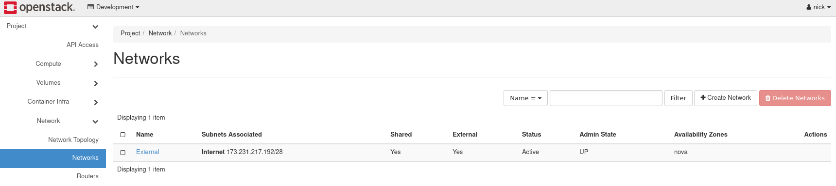
Figure 1: Networks in Horizon
Load the form to create a network, by navigating to Create Network near the top right.
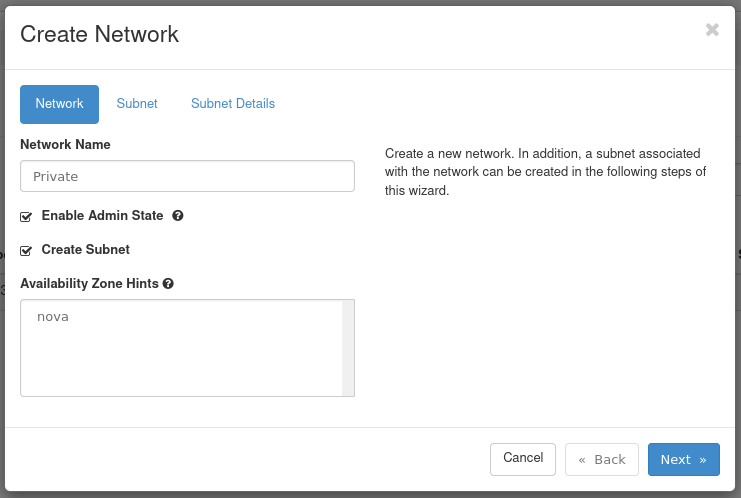
Figure 2: Network Tab
- Network Name: Set a name for the network. This example is called Private.
- Enable Admin State: Leave this checked to enable the network.
- Create Subnet: Leave this checked to create a subnet.
- Availability Zone Hints: Leave this option as default.
Next, move on to the Subnet tab of this form.
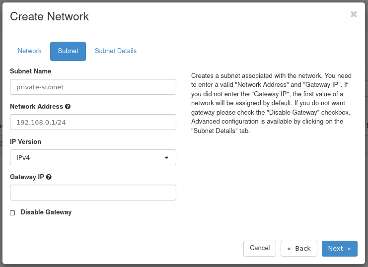
Figure 3: Subnet Tab
- Subnet Name: Set a name for the subnet. This example subnet is called private-subnet.
- Network Address: Select a private network range. For example:
192.168.0.1/24 - IP Version: Leave this as IPv4.
- Gateway IP: This is optional. If unset, a gateway IP is selected automatically.
- Disable Gateway: Leave this unchecked.
Next, move on to the Subnet Details tab of this form.
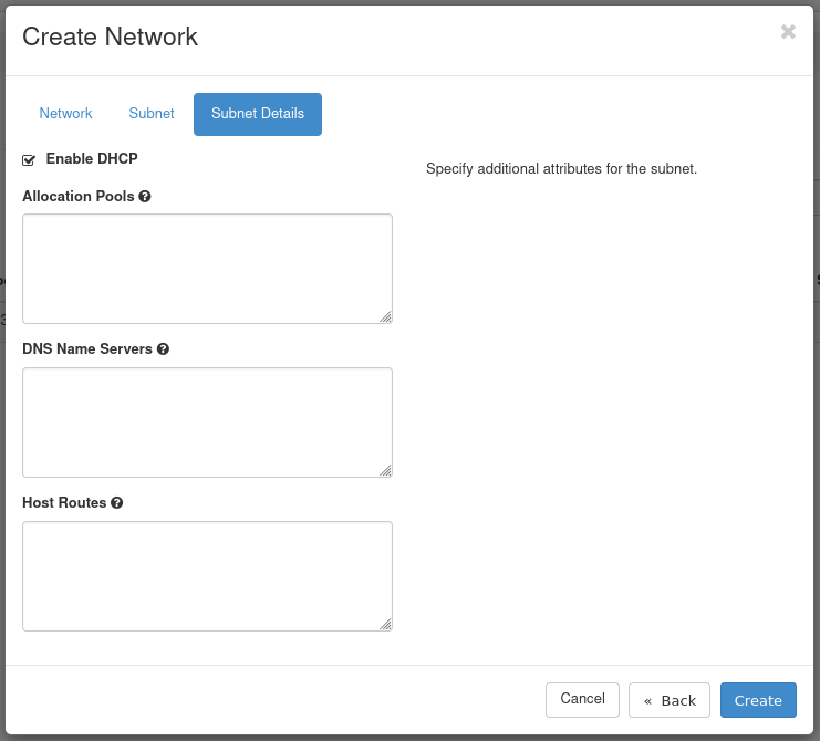
Figure 4: Subnet Details Tab
- Enable DHCP: Leave this option checked.
- Allocation Pools: Optional, can specify the range from which IPs are selected.
- DNS Name Servers: Optional. Specify any DNS name servers here.
- Host Routes: Optional. Specify any host routes here.
Click Create to create the network. Once created, it appears in the list of networks.
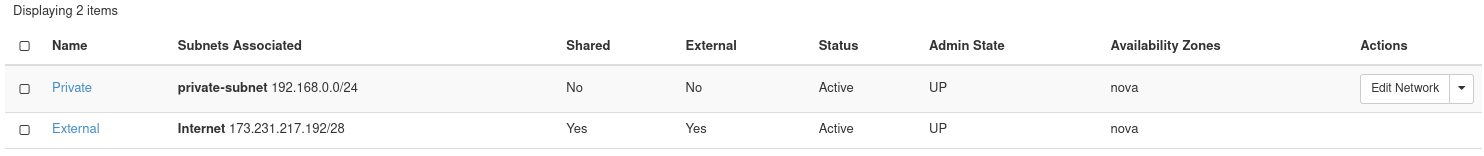
Figure 5: Network Listing
Create a Router
You next need to create a router to bridge the connection between the private network and the public network. The public network is called External.
To create a router, begin by navigating to Project -> Network -> Routers.
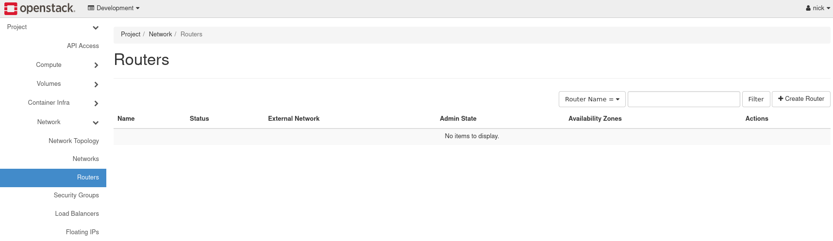
Figure 6: Router Listing
Load the form to create a router by navigating to Create Router near the top right.
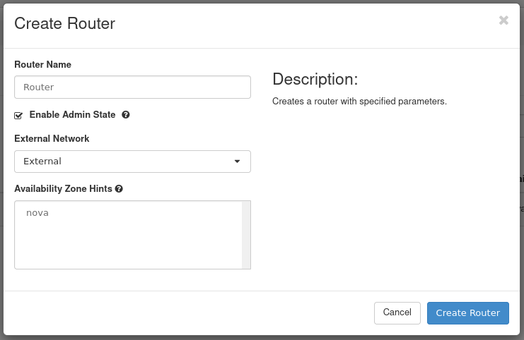
Figure 7: Create a Router
- Router Name: Set a name for the router here. This example router is called Router.
- Enable Admin State: Leave this checked to enable the router.
- External Network: Choose the network External.
- Availability Zone Hints: Leave this as the default.
Once complete, create the router by pressing Create Router.
Connect Router to Private Network
Next, connect the router to the private network, by attaching an interface. Performing this step allows network communication between the Private and External networks.
To attach an interface to the router, first navigate to the list of routers and locate the one previously created.

Figure 8: Router List
Click the name of the router to access its details page. This is where the interface is attached. There are three tabs: Overview, Interfaces, and Static Routes. To attach an interface, navigate to the Interfaces tab then load the form to attach an interface by clicking Add Interface near the top right.
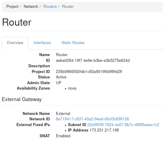
Figure 9: Router Details
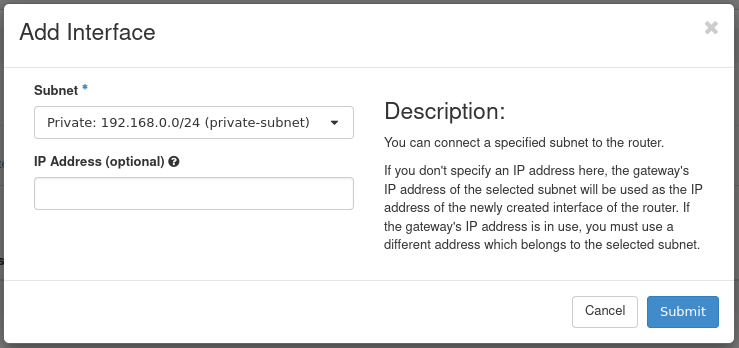
Figure 10: Attach Interface
- Subnet: Select the appropriate subnet. In this example, we choose the private-subnet.
- IP Address: Optional. Specify an IP if required, otherwise one is selected automatically.
Press Submit to attach the Private network to this router. The interface is then attached and now listed.

Figure 11: Interface Listing
View Network Topology
Should you want to visually see the network topology for your cloud, navigate to Project -> Network -> Network Topology.
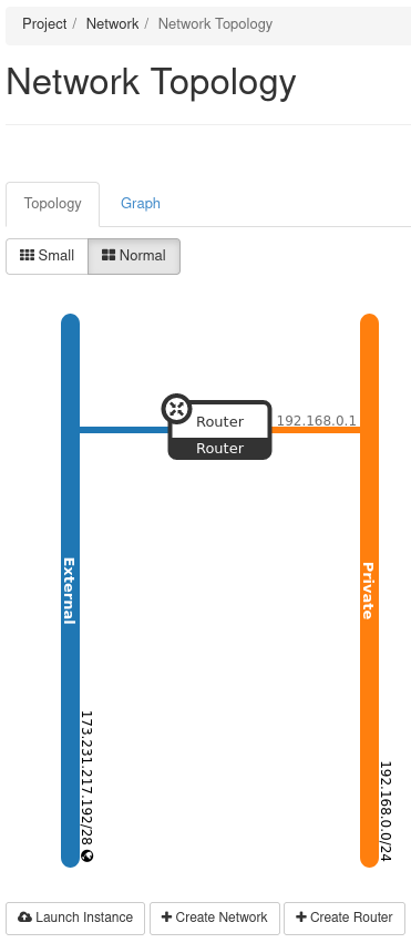
Figure 12: Network Topology
This figure indicates the External network is connected to the Private network through the router called Router.
Security Groups
Security groups allow control of network traffic to and from instances. For example, port 22 can be opened for SSH for a single IP or a range of IPs. In this demonstration, we create a security group for SSH access. This security group is then applied to the instance we later create.
To view and manage security groups, navigate to Project -> Network -> Security Groups.
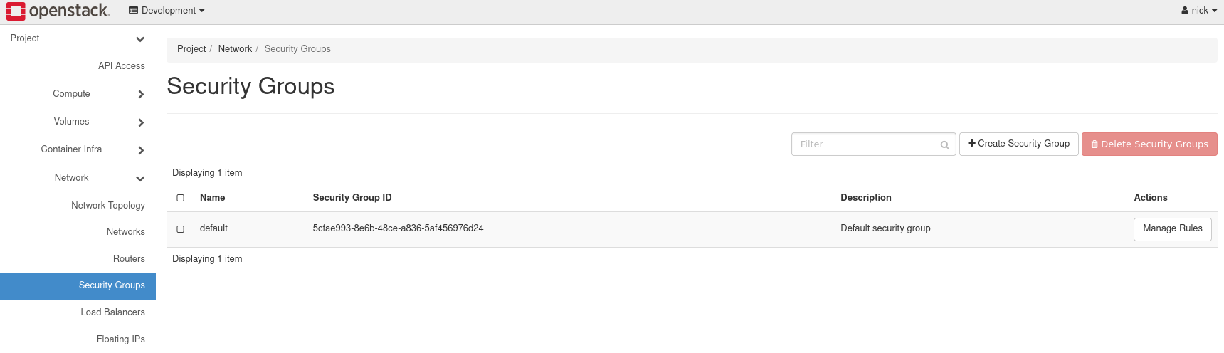
Figure 13: Security Groups
In this cloud, there exists a single security group called default. This security group restricts all incoming (ingress) network traffic and allows all outgoing (egress) network traffic. When an instance is created, this security group is applied by default. To allow the network traffic your instance requires, only open ports as required to just the needed IP ranges.
Create an SSH Security Group
To create a security group for SSH, load the form by navigating to Create Security Group near the top right.
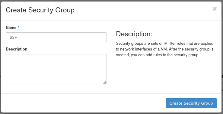
Figure 14: Create Security Group Form
- Name: Specify a name for the security group. This example security group is called SSH.
- Description: Optional. Describe the security group if applicable.
Add Rule to SSH Security Group
After creating the SSH security group, we need to add a rule allowing SSH traffic. This example demonstrates allowing SSH traffic from the first hardware node in this cloud to this instance.
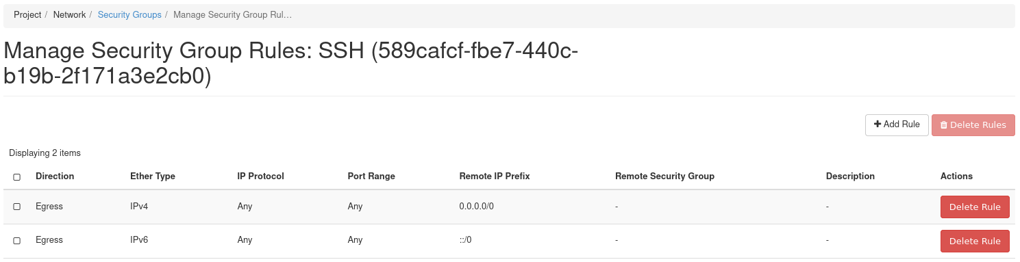
Figure 15: Manage Security Group Rules
To add a rule, load the form by navigating to Add Rule near the top right.
To follow this example, obtain the IP address of the first hardware node of your cloud. You can find this using OpenMetal Central under your cloud's Assets Page. To be consistent, this guide assumes you are working with the first hardware node's IP address and the remaining instruction is created with that understanding.
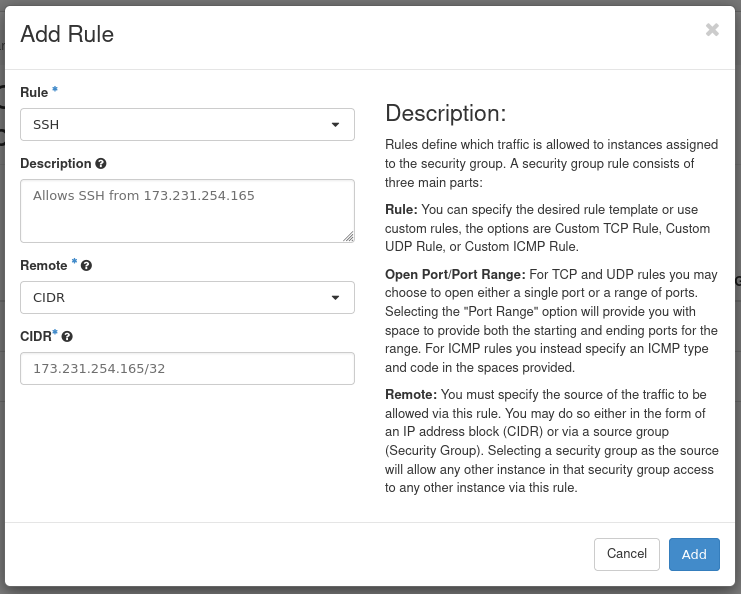
Figure 16: Add SSH Rule
- Rule: Select SSH. When adding rules you can choose from predefined options. In this case, we choose the SSH rule from the first drop down.
- Description: Optional. Provide a description of the rule.
- Remote: Select CIDR.
- CIDR: Specify the IP address of your first hardware node.
Press Add to add this rule to the security group. This concludes creating the security group.
How to Create your First Instance
With the previous steps complete, almost everything is in place to create your first instance.
Prerequisites
SSH Public Key
An SSH public key is required to access an instance over SSH. This key is injected into the instance when created. An SSH key cannot be added to an already running instance.
For this guide, we are arranging it so this instance can be accessed over SSH from one of the cloud's hardware nodes. Due to this, you must create an SSH key pair in one of the hardware nodes. The public portion of that key pair is associated with the instance created later in this guide. To learn how to create this key pair, see the supplementary guide: Create SSH Key Pair for an OpenStack Control Plane Node.
Operating System Image
Several operating system images are available with which to create instances. To view available options, navigate to Project -> Compute -> Images. To upload your own images, see How to Upload Operating System Images using Horizon.
Create your First Instance
To create the first instance, begin by navigating to Project -> Compute -> Instances.
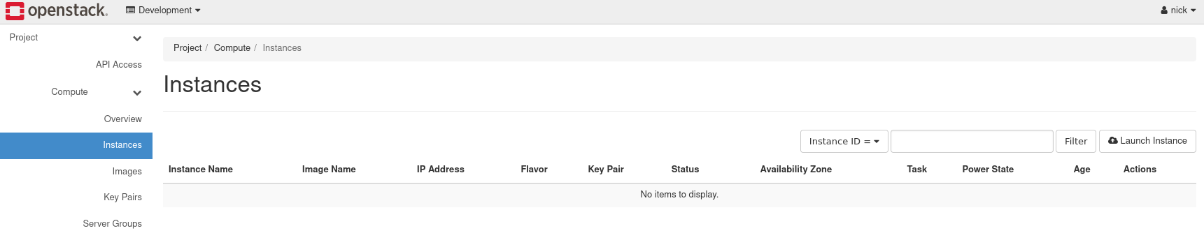
Figure 17: Instances
Pull up the form to create an instance by navigating to Launch Instance near the top right.
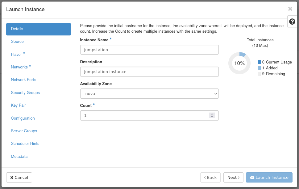
Figure 18: Instance Details
- Instance Name: Set a name for the instance. This example instance is called Jumpstation.
- Description: Optional. Set a description if this applies.
- Availability Zone: Leave as the default, which is Nova.
- Count: Controls the number of instances spawned. This example creates a single instance.
Next, move to the Source tab allowing you to specify an operating system image.
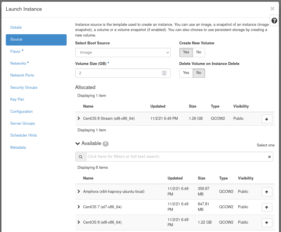
Figure 19: Instance Source
- Select Boot Source: In this example, we use Image as the boot source.
- Create New Volume: Leave this checked as Yes. This creates a
new Cinder volume where the specified operating system image is
copied into it. The volume ultimately exists with the Ceph cluster,
in the
vmspool. - Volume Size: Allow the system to determine this for you.
- Delete Volume on Instance Delete: Leave this option set as No. If checked, when the instance is deleted, the volume is as well.
Under the Available section, select the appropriate operating
system. This example uses CentOS 8 Stream (el8-x86_64).
This concludes configuring the instance's source. Next, move to the Flavor tab.
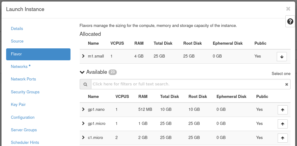
Figure 20: Instance Flavor
Flavors are a way to define the VCPUs, RAM, and Disk space used by an
instance. Pre-built flavors are available for you. For this step, select
an appropriate flavor from the options under the Available heading.
This example uses the m1.small flavor.
Next, move to the Networks tab.
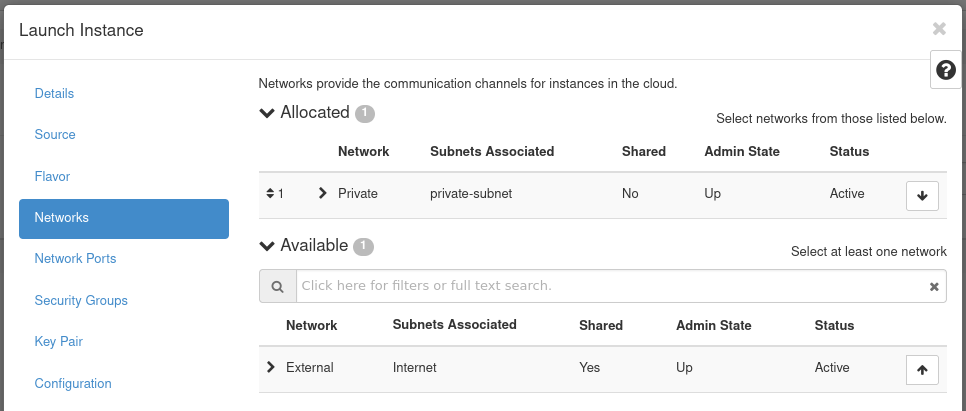
Figure 21: Instance Networks
In this section, you specify the network with which the instance is associated. For this example, select the Private network created previously. You can choose the External network as well, but this is generally recommended against in favor of using a floating IP should your instance require Internet connectivity.
Note! Only expose portions of your network as necessary. This reduces the attack surface and improves application security. If a private network is not created and an instance is created in a default cloud, it is associated with the External network. This means the instance consumes a public IP and it could be reached over the Internet.
Next, skip over the Network Ports tab and move to the Security Groups.

Figure 22: Instance Security Groups
This is where you select security groups for the instance. This example uses the SSH security group in the Availalble section.
As the final step, move to the Key Pair tab.
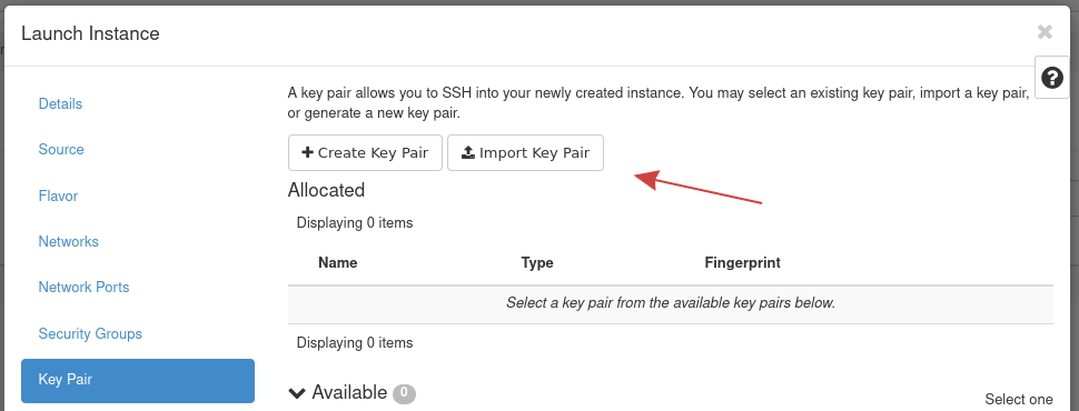
Figure 23: Instance Key Pair
In this section, you specify an SSH public key to inject into the instance. You can upload your key at this stage using this form using the Import Key Pair button. For this demonstration, we use Import Key Pair to import the existing SSH public key created previously for one of the control plane nodes.
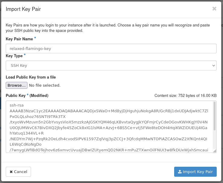
Figure 24: Import Key Pair Form
- Key Pair Name: Set a name for the SSH public key. This example
public key is called
relaxed-flamingo-key. - Key Type: This example uses an SSH Key key type.
- Load Public Key from a file: Specify the location of the public key on your machine.
- Public Key: Here you can paste in the public key.
Once the public key is imported, create the instance by pressing Launch Instance.
Note! -- We skip some sections of the instance creation form as they are not required for this demonstration.
The instance goes through a build process. Allow a few minutes for this to occur. When complete, the instance appears in the Instances Listing page.

Figure 25: Instance Listing
Assign and Attach Floating IP
The instance created previously is associated with a private network. Presently, the only way to access this instance is to connect to it from with the cloud's hardware nodes. Another option for connecting is to use a floating IP. In this section, we demonstrate how to allocate a floating IP and attach it to this instance.
To allocate a floating IP, first navigate to Project -> Network -> Floating IPs.
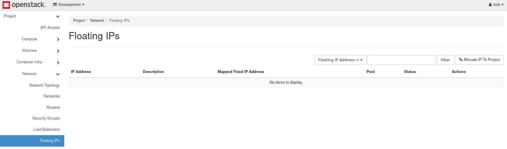
Figure 26: Floating IPs Listing
Next, load the form to allocate a floating IP by pressing Allocate IP to Project.
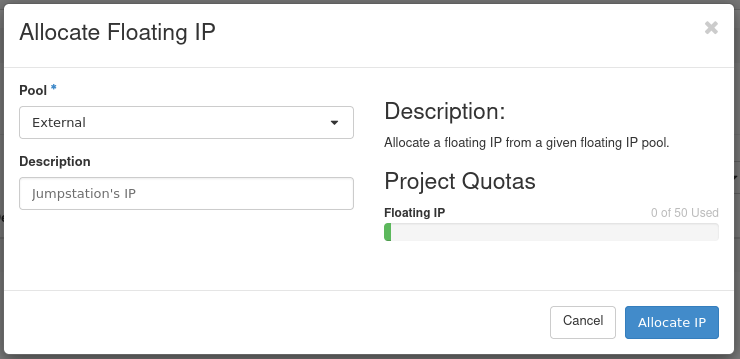
- Pool: Select External for the allocation pool.
- Description: Optional. Set a description for the floating IP.
Press Allocate IP to add this floating IP address for use.
Next, in the same section, allocate the IP to the Jumpstation instance by clicking the Associate button at the far right.

Figure 27: Associate Floating IP
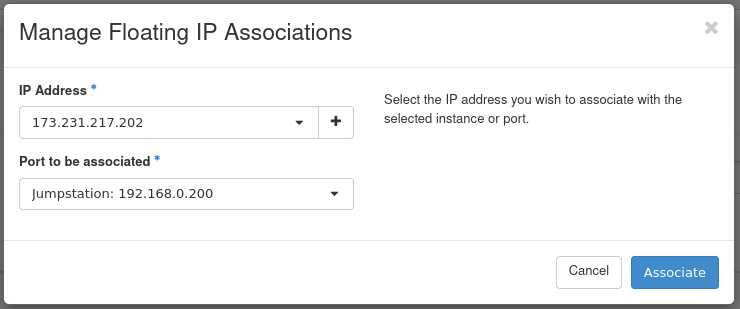
Figure 28: Manage Floating IP Associations
- IP Address: This field comes pre-selected with the floating IP so there's no need to change anything here.
- Port to be associated: Select the instance created previously. In this case, we use the Jumpstation instance.
This concludes allocating the floating IP to the instance. This instance is now accessible over SSH from the first hardware node of your cloud.